Oyster
Bay Historical Society Spring 2001 Edition of the Freeholder
In the Spring 2001 edition of the
Freeholder, Walter Karppi wrote an interesting article explaining the
history, function and operation of railroad turntables. In essence,
the turntable was used to turn steam locomotives in the opposite direction
for a return trip. Walter discussed the
Danbury
Railroad
Museum
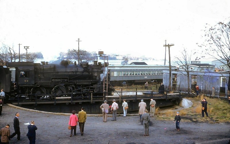
ís turntable and the way crowds gathered around to watch the operation.
He likened the
Danbury
turntable to what the Oyster Bay turntable will be when it is restored and
placed into service as part of the
Oyster Bay
Railroad
Museumís facilities. |

Cover |
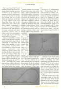
Page 1 |
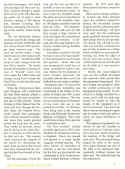
Page 2 |
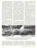
Page 3 |
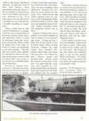
Page 4 |
Long Island Sunrise Trial Chapter - NRHS
The185th Anniversary of the Long Island Rail Road
Dave Morrison's, LIRR Historian, article discusses the
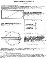
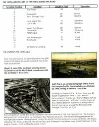
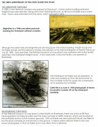
numerous LIRR turntables, function, and location with photos. |
 |
 |
 |
 |
 |
|
The
Oyster Bay
turntable
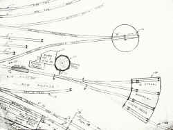 The turntable now in the Oyster Bay Railroad Museumís yard is actually the second turntable at this location. The LIRR reached Oyster Bay in 1889, having been extended from Locust Valley . That
50' turntable had been in Locust Valley since 1869 and after 20 years, it was moved with the expansion of LIRR service to Oyster Bay
in 1889. A four stall enginehouse was built in the same year. The turntable was located northwest of the
engine house. In 1904 the old turntable was torn out and a new 70 foot long turntable was installed north of the
engine house as an air operated unit until an electric motor was installed
in 1932. In this connection, see the sketch below drawn by the late LIRR Conductor Bob Emery, whose collection of maps, drawings and photographs is at Stony Brook University The turntable now in the Oyster Bay Railroad Museumís yard is actually the second turntable at this location. The LIRR reached Oyster Bay in 1889, having been extended from Locust Valley . That
50' turntable had been in Locust Valley since 1869 and after 20 years, it was moved with the expansion of LIRR service to Oyster Bay
in 1889. A four stall enginehouse was built in the same year. The turntable was located northwest of the
engine house. In 1904 the old turntable was torn out and a new 70 foot long turntable was installed north of the
engine house as an air operated unit until an electric motor was installed
in 1932. In this connection, see the sketch below drawn by the late LIRR Conductor Bob Emery, whose collection of maps, drawings and photographs is at Stony Brook University
General Notice 1-48, Effective 2/15/1983, Turntable Track, Oyster Bay, out
of service. Info: Jeff Erlitz
Originally it was a 2 phase 208 volt. Currently re-wired to 3 phase 240
volts which is a current standard. Itís only 60 HP and works very well.
Info: Gary Farkash
See more at the
Oyster Bay Railroad Museum Equipment |
|
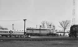 FM
CPA24-5 #2402 on Oyster Bay turntable 3/14/1953 (Faxon-Keller) FM
CPA24-5 #2402 on Oyster Bay turntable 3/14/1953 (Faxon-Keller)
|
|
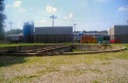 The turntable
restoration now at the Oyster Bay Railroad Museumís yard. 07/27/2008
Photo: JJ. Earl The turntable
restoration now at the Oyster Bay Railroad Museumís yard. 07/27/2008
Photo: JJ. Earl
|
|
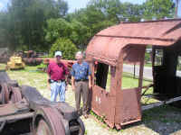 JJ.
Earl (l) and Mark Smith (r) 07/2008 JJ.
Earl (l) and Mark Smith (r) 07/2008
|
|
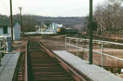 .Oyster
Bay turntable - view W 2/1973 Photo: Steve Rothaug .Oyster
Bay turntable - view W 2/1973 Photo: Steve Rothaug
|
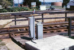 Turntable Controls - Oyster Bay 8/21/1973 (Madden-Keller)
|
|
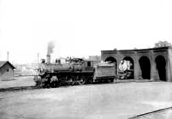 The
engine house lasted until it was demolished on
August 4, 1929
. No engine house was built
afterwards. There is only one
known existing photograph of the Oyster Bay
engine house. Collection: David Keller The
engine house lasted until it was demolished on
August 4, 1929
. No engine house was built
afterwards. There is only one
known existing photograph of the Oyster Bay
engine house. Collection: David Keller
|
|
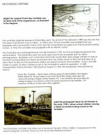
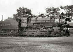 The 1904 turntable was originally powered by a pneumatic motor.
The turntable operator would hook up a hose from the air compressor
of a nearby steam locomotive to the turntable motor, which then could be
operated by air pressure. Railroad
historian Art Huneke has an LIRR 1945 Depreciation document showing that
the
Oyster Bay
turntable was electrified in 1932. It
was operated by electric motor until it was taken out of service sometime
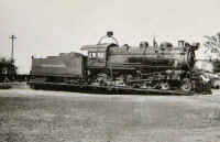
in the 1970s. The photo, taken
by John Krause on August 12, 1948 shows steam locomotive #29 being turned
on the Oyster Bay turntable. The 1904 turntable was originally powered by a pneumatic motor.
The turntable operator would hook up a hose from the air compressor
of a nearby steam locomotive to the turntable motor, which then could be
operated by air pressure. Railroad
historian Art Huneke has an LIRR 1945 Depreciation document showing that
the
Oyster Bay
turntable was electrified in 1932. It
was operated by electric motor until it was taken out of service sometime
in the 1970s. The photo, taken
by John Krause on August 12, 1948 shows steam locomotive #29 being turned
on the Oyster Bay turntable.
|
|
The Oyster Bay
turntable, is in the planning stages of a full restoration. For the years that this turntable was in operation, it was
basically open to public view. Engineers
such as the late Cecil Craft would often allow eager kids to ride on the
front running board of his steam locomotive from the station down to the
yard and then heíd allow them to stay on the locomotive while it was
being turned on the turntable. In
fact, the LIRR made it a policy to allow children to view the turntable
operation. In LIRR
Transportation Notice #1330 issued on
August 3, 1965
the LIRR employees were advised as follows: |
|
ďOyster Bay
Turntable * Station Agent will meet group [school children from Queens
Public School #40] and conduct tour of Oyster Bay facility where they will
witness the turning of Engine #516. Crew
should be advised to delay the turning of Engine a few minutes to allow
the group to get down to the turntable.
110 containers of milk at 10 cents eachÖĒ |
|
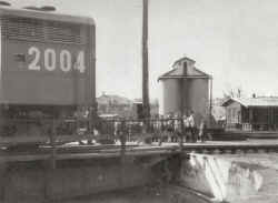 Significant
to this article is a photo that appeared in the Summer 2002 Freeholder
article on the history of the Oyster Bay Train Station.
That photo shows school children at the Oyster Bay
turntable in the mid 1950s. Collection: Arthur Huneke Significant
to this article is a photo that appeared in the Summer 2002 Freeholder
article on the history of the Oyster Bay Train Station.
That photo shows school children at the Oyster Bay
turntable in the mid 1950s. Collection: Arthur Huneke
|
|
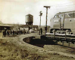 Another
photo that shows a field trip of school children at the Oyster Bay
turntable c.1953-54. Collection: Gary Frakas Another
photo that shows a field trip of school children at the Oyster Bay
turntable c.1953-54. Collection: Gary Frakas
|
 LIRR
C420 #201 approaching the turntable LIRR
C420 #201 approaching the turntable
1970 - Photo/Archive: John Schaub
Note: Bunk House at left.
|
|
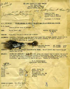
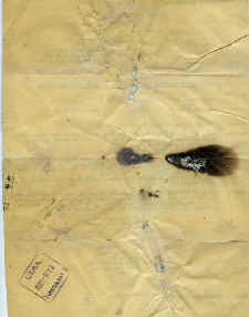
Letter when cleaning up my office inside the Oyster
Bay ticket office during the late 1990s. It has been damaged, but I guess
that adds an air of authenticity to the document.
The letter had the ticket validator stamp on the
reverse side 8/05/1965
The top of the letter has a pencil-hand-written note:
"...Small
girl injured while boarding train at Union Hall Street. Fell between
train and platform..."
Archive: Dave Morrison |
 |
 |
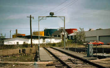
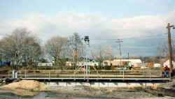
Oyster Bay yard- turntable 5/13/1986 Photo: Edward Hand |
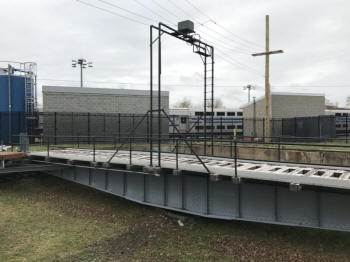
Oyster Bay turntable bridge - 2017
Photo/Archive: Andrew Ciavarella |
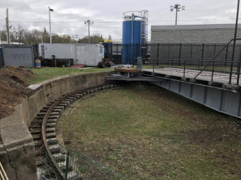
Oyster Bay turntable pit 2017
Photo/Archive: Andrew Ciavarella |
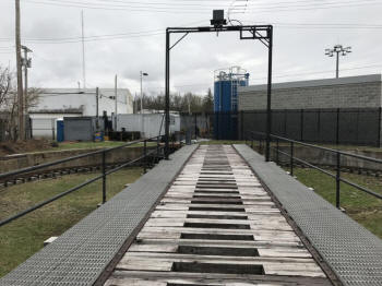
Oyster Bay turntable - 2017 Photo/Archive: Andrew Ciavarella |
The 3 phase-240 volt power comes in from
the provider to our circuit panel where an independent circuit goes to the
TT lockout panel box where the ground and 3 power conductors go up to the
top of the pole. These wires are then strung across the top of the TT
bridge arch (4 wires).
The 3 power and 1 ground wires are
tapped to provide a connection into the non-moving brushes which send
power through the 4 moveable brass circular rails. These rails are
insulated from each other and each one has a stud at the very top where
individual wire conductors are connected to send power from the collector
box at the top of the arch down through one leg of the arch directly to
the motor. At this point, the motor is connected to the control stand by
wires underneath the stand.
The motor has a series of wires which
then get connected to the resistor bank to enable forward and reverse
drive. Info Gary Farkash
|



 .
.


